Design and Development of High Voltage Ramp Generator for Driving PZT Transducer

หน่วยปฏิบัติการวิจัยมาตรวิทยา และฟิสิกส์ของอุปกรณ์ ภาควิชาฟิสิกส์ คณะวิทยาศาสตร์
มหาวิทยาลัยเกษตรศาสตร์
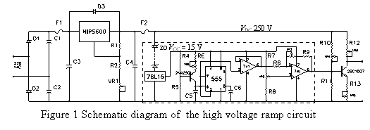
| โครงการวิจัยนี้ ต้องการออกแบบสร้างเครื่องกำเนิดสัญญาณฟันเลื่อยความต่างศักย์สูง เพื่อขับเพียโซแทรนสดิวเซอร์ชนิด ลีด-เซอร์โคเนต-ติตาเนต (Pb(ZrXTiX-1)O3: PZT) รูปทรงกระบอกกลวง ซึ่งเป็นตัวควบคุมตำแหน่งกระจก เงาใน มาตรแทรกสอด เฟบรี-เปโรต์ โดยมีเป้าหมายให้เครื่องกำเนิดสัญญาณที่สร้างขึ้นมีราคาถูก แต่มีคุณภาพใกล้เคียงกับเครื่องที่ผลิตจากต่างประเทศ โดยเฉพาะด้านเสถียรภาพของความถี่และความเป็นเชิงเส้นของสัญญาณ ปัญหาในการวิจัยนี้จึงอยู่ที่เทคนิคในการออกแบบภาคต่างๆ ของวงจร การแก้ปัญหาการรบกวนจากภายใน ปัญหาจากสัญญาณแทรนเซียน การรักษาเสถียรภาพของความต่างศักย์และความถี่ ตลอดจนการแกว่งกวัดของสัญญาณเนื่องจากการเรโซแนนซ์ของตัวภาระที่เป็น PZT แทรนสดิวเซอร์ คำตอบที่ได้จากการวิเคราะห์และทดสอบวงจรหลายๆ แบบ คือ "เลือกใช้วงจรง่ายๆ ที่มีอุปกรณ์น้อยที่สุด" ในด้านการประยุกต์ เครื่องกำเนิดสัญญาณชนิดนี้ ยังสามารถใช้กับงานวัดวิเคราะห์สมบัติทางไฟฟ้าของอุปกรณ์ต่างๆ ได้มากมาย ไปจนถึงการใช้เป็นวงจรขับ PZT แทรนส์ดิวเซอร์ รูปร่างอื่นๆ เช่น ใช้ในการกำหนดตำแหน่งระดับนาโน (Nano-positioning) Introduction: Methodology: 1. Circuit design: The circuit has two significant parts, the high voltage part and a linear ramp generation part. The linear ramp is generated by the timer IC 555 (1). It is operated in mono stable mode but the charging of a timing capacitor is done via a constant current source. Since, the timing capacitor voltage is is vc = q/C
Varying VRE control rise time and frequency. Ramp signal from the capacitor is very sensitive. In order to keep its linearity, a voltage follower is used for buffering before amplification by inverting amplifier. The high voltage part receives voltage of 600 V from full-wave voltage doubler circuit. High voltage regulator, HIP5600, is employed to control and regulate output voltage. It is able to adjust voltage output from 50 V to 400 V. High voltage signal driver is 2SC1507, 300 V, 15 W NPN silicon transistor. The inexpensive transistor is operated as class A potential divider direct coupling amplifier. Generally, most of class A amplifier has nonlinear response. In this case, small signal approximation shows the linear characteristics of 2SC1507 in the region of very low IC and high VCE. 2. The circuit.
3. Signal analysis
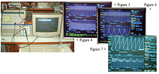
method. After several months of finding and testing for suitable device we already build the generator test circuit (Figure 2). However, the signal (Figure 3) is better than our forecasted signal. The signal analysis instrument setup is shown in Figure 4. FFT analysis of the generated ramp at 1.000 Hz is shown in Figure 5, In this figure, first twenty Foureir-components shown its very clean signal.
Figure
7, the FFT analysis of 1.000 Hz ramp from a well-known brand name.
The small Fourier components between the odd harmonics peak show
some characteristic signal that must be investigated further. However,
Our test
|


